|
|


Interactive Voice Response
This section of our technical library presents information and documentation relating to IVR and interactive voice response software as well as automatic call answering solutions.
Business phone systems and toll free answering systems (generally 800 numbers and their equivalent) are very popular for service and sales organizations, allowing customers and prospects to call your organization anywhere in the country.
Our PACER and Wizard IVR systems add another dimension to our call center phone system solutions. An Interactive Voice Response (IVR) processes inbound phone calls, plays recorded messages including information extracted from databases and the internet, and potentially routes calls to either in-house service agents or transfers the caller to an outside extension.
All You Wanted to Know About T1 But Were Afraid to Ask
By Bob Wachtel
Introduction
We are experiencing a breakneck growth in the interconnection of personal computers, terminals and telephones in the business environment. T1 technology is proving to be a cost-effective means of linking voice and data, both inter-office and intra-office, and serves as an alternative to high speed modems for data transport. There is significant discussion these days about "T1 Gateways" and "T1 trunks" as the cost from the various phone companies of these services goes down. Users are discovering that it costs less to have a T1 trunk than a series of leased telephone lines in a point-to-point topology. This increase in the use of T1 requires a fundamental understanding of the technology.
Background
T1 is a high speed digital network (1.544 mbps) developed by AT&T in 1957 and implemented in the early 1960's to support long-haul pulse-code modulation (PCM) voice transmission. The primary innovation of T1 was to introduce "digitized" voice and to create a network fully capable of digitally representing what was up until then, a fully analog telephone system.
Perhaps the way to really begin this discussion is to discuss the AT&T Digital Carrier System referred to as "ACCUNET T1.5". It is described as a "two-point, dedicated, high capacity, digital service provided on terrestrial digital facilities capable of transmitting 1.544 Mb/s. The interface to the customer can be either a T1 carrier or a higher order multiplexed facility such as those used to provide access from (fiber optic) and radio systems."
So in the basic definition there is the discussion that there is a "higher order" or hierarchy of T1. There is T1 which is, as we have discussed, a network that has a speed of 1.544 Mbps and was designed for voice circuits or "channels" (24 per each T1 line or "trunk"). In addition, there is T1-C which operates at 3.152 Mbps. There is also T-2, operating at 6.312 Mbps, which was implemented in the early 1970's to carry one Picturephone channel or 96 voice channels.
There is T-3, operating at 44.736 Mbps and T-4, operating at 274.176 Mbps. These are known as "supergroups" and their operating speeds are generally referred to as 45 Mbps and 274 Mbps respectively.
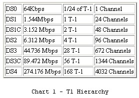
The general T-Carrier hierarchy appears in Figure 1 and is detailed in Chart 1.
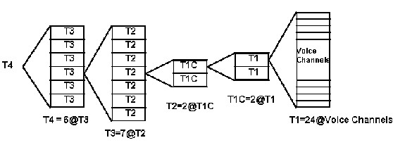
Figure 1 - T-Carrier Hierarchy
For mathematical reasons, a voice channel was selected to be at 64 Kbps. 24 of these channels is a composite of 1.536 Mbps, not 1.544 Mbps! Why is there a difference? The reason is that after a byte (8 bits) of data is sent from each channel (24 * 8 = 192 bits) there is an extra bit used for synchronizing called a Frame bit - hence 193 bits are sent and this increase of 1 bit per 192 causes the speed to increase to 1.544 Mbps.
The fundamental frame of T1 is shown in Figure 2.
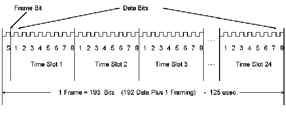
Figure 2 - Frame Organization
Well, you might ask, 1.544*2 = 3.088 Mbps and not 3.152 Mbps for T1C, how come? Well, the answer is that the T1C frame is made up of 1272 bits and is quite different from the 193 bit frame of the T1 data stream. It should be pointed out that the frame length of T1C and higher signals are not related in any technical way to the T1 stream which is treated simply as a string of bits. The simplistic diagram in Figure 1 is correct from an organizational point of view and does not show the relationship of the formatted data.
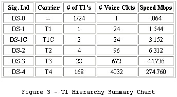
Now I have been using the term "T1 data stream". To be consistent with AT&T parlance, a "T1 data stream" is called a "DS1". Equally, a T1C stream is referred to as "DS1C", etc. Another summary chart to show the relationship is in Figure 3:
A convenient way to think of T1 is from the first two layers of the ISO (International Standards Organization) OSI(Open System Interconnect) model: the Physical and Logical layers. The Physical layer focuses on the electrical characteristics such as signal shape, voltage levels, etc. The logical layer deals primarily with the format issue - how is the data extracted from the low-level protocol?
The designation "DS" in Figure 3 refers to "Digital Signals" and describes the physical layer. The designation "T" refers to the type of carrier that is being used. Often these are used interchangeably but that technically is not correct.
On the topic of standards, T1 has been specified first by AT&T and second, by ANSI (American National Standards Institute). The European equivalent of T1 is called CEPT and is a CCITT standard. As a point of interest, the CEPT standard is at 2.048 Mbps and does not use a "master clock". In the U.S., the three major carriers each have a single "master T1 clock" from which all the others are derived. In the U.S., all T1 clocks are "slave" to this master clock. The problem that occurs is when someone wants to interconnect a T1 network provided by MCI to a T1 network provided by Sprint. This requires what is known as an elastic buffer and this is built into most T1 devices.
When someone says they are running T1, they may be saying several different things: The may mean that they have a network that is passing data at 1.544 Mbps; they may mean that they have a network that conforms to the T1 electrical interface specification (DSX-1), or that they have a network that passes data that conforms to one of the several framing formats (D4, ESF, etc.). More likely than not, they mean all three but their concentration may be on only one of these items. The confusion in the user community is a result of the interchangeability of words and the confusing requirements for connection to the AT&T system.
Services and Quality
AT&T through ACCUNET T1.5 offers several services besides the already mentioned point-to-point service. There are four "transfer arrangements" that can be purchased:
- 1. Customer ability to change terminating location of T1 link with AT&T assistance (either signal or dial)
- 2. M24 Multiplexing allowing the user to connect up to 24 channels to individual switched and non-switched services offered by AT&T.
- 3. M44 Multiplexing allowing the user the capability to combine 2 T-1 lines, each carrying up to 22 channels to 1 T1 line using Bit Compression Multiplexing (BCM).
- 4. Customer Controlled Reconfiguration (CCR) allowing the customer to dynamically allocate circuits without AT&T assistance.
These services allow the user to have T1 trunks in several cities and allow data transfer to each. This along with the T1-Mux (to be discussed later) forms the modern T-1 network.
Associated with the lower costs of T1, the guaranteed quality of the network is also superior to leased lines. By specification, AT&T states that the performance objective is 95% Error Free Seconds (EFS) on a daily basis and the availability objective is 99.7% on a yearly basis.
Channel Banks and Formats
A digital source, or terminal, is the equipment that generates digital signals for transmission through the digital network. The large majority of digital sources now produce a DS-1 signal. The D4 Channel Bank is an example, although it can produce signals at other rates as well.
The reference to the term "Channel Bank" is made quite often in the T-1 language. The type of Channel Bank is important since it defines the type of formatting that is required. For example, a D4 Channel Bank must have a DS-1 signal with data formatted in accordance with the D4 format.
The purpose of a Channel Bank in the telephone company is to form the foundation of multiplexing and demultiplexing the 24 voice channels (DS0). The D-type Channel Bank is used for digital signals. There are five kinds of Channel Banks that are used in the System: D1, D2, D3, D4, and DCT (Digital Carrier Trunk).
A transmitting portion of a Channel Bank digitally encodes the 24 analog channels, adds signalling information into each channel, and multiplexes the digital stream onto the transmission medium. The receiving portion reverses the process. As these were designed as voice circuits, the assumption is that the digital data is PCM voice and that the voice is companded and expanded through the use of CODECs. D1 banks (later called D1A) were first installed in 1962 and their success led to modifications of D1B and D1C. The original D1A,B, and C banks used 7 bits for each voice sample and one bit in each code word for carrying the signalling (off hook, ring, etc). When it became desirable to connect several T1 transmission spans together, the performance was not too good. In addition, it was realized that providing signaling information in every code word was wasteful since 8,000 bits per second was not required to provide the signaling information for a channel; the signalling information simply did not change that quickly.
As a result of these conditions, another modification to the D1 series (D1D) and the new D2 channel bank were developed. The D2 bank uses all eight bits of every time slot to encode the analog signal except for selected frames. Supervisory and signalling information is sent by using the least significant bit from the code word in each channel every sixth frame. The companding characteristic also was changed to give better performance. The D2 bank increased the packing density to 96 channels in the same space as the 72 channels for a D1 bank.
D3 and D4 banks were motivated by advances in ICs, allowing packaging of 144 channels in a single bay. Following the D4 bank, advances in technology resulted in the development of the Digital Carrier Trunk unit, or DCT. It was developed by the Bell System to be smaller, lower cost, and easier to maintain than the D4 channel bank.
The D1 type channel bank (D1A,B,C) placed alternate 1's and 0's in the 193rd bit position. It was assumed that random data would not contain this pattern, in bits spaced exactly 193 bits apart, for any significant length of time. The receiving device would find the 193rd bit by using a simple search technique. This algorithm had the advantages of circuit simplicity and speed. In the early 1960's, there were few commercially available ICs for building complex logic functions, and elementary designs cost less. The disadvantages of this technique were rapidly uncovered when equipment was installed in actual customer sites. Certain standard analog tones, such as the 1000 Hz test tone, applied to one or more voice channels and digitized by Channel Bank, created an alternating one and zero pattern every 193 bits in one or more voice channels. It was possible for the terminal to lock up on the incorrect pattern. This condition, affecting all 24 channels, could last until the test tone was removed. The 1000 Hz tone has been changed to a 1004 Hz test tone.
By the time this problem became apparent, it had been decided to use T-carrier for toll quality telephony, which required more precise coding techniques. D1 channel banks used seven bit encoding for voice signals, and an eighth bit for signalling. The new format provided for eight bit coding most of the time (5/6 frames) and seven bits only in one frame out of six. This is known as 7 5/6 coding with "robbed bit" signaling and was first implemented in the D2 channel bank (D1D is a retrofit of D1 channel banks with D2 capability).
Besides the "false frame" problem, D2 bank designers were faced with a new set of problems. The new format required two steps; first, find the 193rd bit, and second, find the sixth and 12th frame in a 12-frame sequence. The time required to find the proper bit sequence rises exponentially as the number of bit positions between frame bits increases. Although we still use every 193rd bit, it is time-shared between the terminal framing pattern (odd numbered frame bits) and the superframe alignment pattern (even numbered frame bits). Finding the 193rd bit position was still based on an alternating 1's and 0's pattern, but now it only appeared in every other 193rd bit.
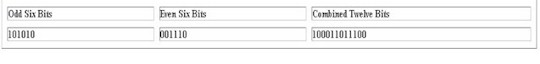
The new technique provided for increased "false frame" protection. The downside of the technique was that the time to reframe was much longer. With the D2 format the maximum average reframe time (MART) would be about 200 milliseconds. This was too much time to be out of service so new algorithms were developed that decreased the time to 50 msec which is now the specification standard. Succeeding channel bank equipment (D3 and D4) used the same framing sequence as D2. In fact, the Superframe Format is most often referred to as the D4 frame format even though it began with D2. This sequence defines a "superframe" consisting of two interleaved patterns. The terminal framing pattern ("F" bit) is a repeating ones and zeros in odd numbered frames and the superframe alignment pattern ("S" bit) is "001110" in the even numbered frames. This results in a 12-bit superframe pattern of:
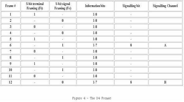
The D4 Format is shown in Figure 4 below. Notice that the "F" bit and the "S" bit are all called "S bits". While this is confusing, it is a terminology remnant of the time when there were only "S" bits (vis-a-vis D1 format).
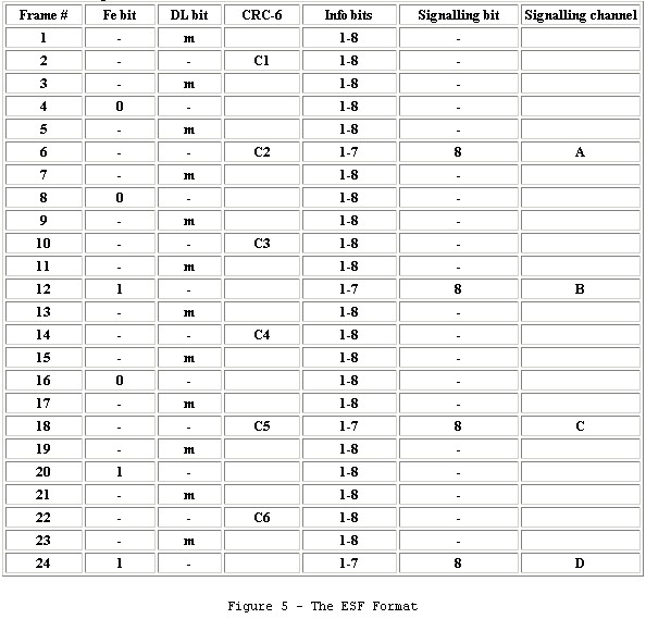
As early as 1979, AT&T proposed the Extended Superframe Format be implemented on its T1 circuits in order to provide in-service diagnostic capabilities as well as improved false frame protection. With ESF, the 193rd bit is now time shared by three functions: frame synchronization bits; CRC-6 bits; and Facility Data Link (FDL) bits. Frame synchronization bits are carried in six of the 24 bit positions provided by the 193rd bit. These are in the 4th, 8th, 12th, 16th, 20th, and 24th positions and the pattern is "001011". This simple six-bit pattern performs both the "F bit" and "S bit" functions of the D4 superframe. "False frame" sensitivity is eliminated by using the CRC-6 error checking bits to determine which of several "candidates" for the frame bit are the actual 193rd bit. CRC-6 uses a mathematical algorithm to check the contents of the entire superframe (all 4632 bits) and obtains a 6-bit (hence its name) coded "signature" for those data bits.
The FDL may be used for any purpose, but is ideally suited for communicating ESF performance information from local, remote, and intermediate equipment along a facility and for sending control commands for protection switching, network and remote equipment configuration, etc. In essence it is a 4 Kbps channel embedded in the T1 format. Bellcore documement TR-TSY-000194 (Extended Superframe Format Interface Specification - December 1987), ANSI T1.403-1989, and AT&T Publication 54016 describes how this channel may be used. This includes the format of the messages , commands, and responses. Most CSU's today interpret these commands and execute the appropriate responses. The ESF Format is shown is Figure 5.
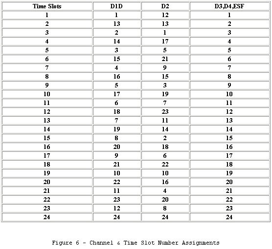
The chart shown in Figure 6 shows the differences between D1 through ESF formats. As most equipment today is either D4 or ESF, the data for D1 and D2 is displayed only for completeness.
Signal Shapes and Codes
A Digital Cross-connect (DSX) consists of equipment frames (patch panels) where cabling between system components is connected. Each digital signal is defined for and handled by its own cross-connect. Thus, for example, DSX-1 is used to interconnect equipment operating with DS1 signals.
The pulse shape of a DS1 pulse is defined at the DSX-1 cross connect. AT&T Publication 43801 describes the requirement of this pulse to drive from 0 to 655 feet of 22 gauge ABAM cable between the channel bank and the DSX-1. The maximum time of reframe time is defined at 50 msec. Actually the DS-1 pulse is a slightly relaxed version the DSX-1 pulse mask. Figure 7 shows the specification (less template) of the DSX-1 signal and how it compares to the DS-1 signal specification.
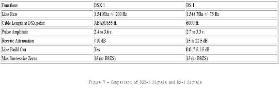
The ANSI standard T1.403-1989 is different yet again. Fundamentally the signals and the templates (signal shapes) are pretty much the same. Modern IC manufacturers have insured that their products meet all of the specs. When we are communicating to the CO or to the carrier we are using DS-1; when we are regenerating the signal after the demarc, we are using DSX-1.
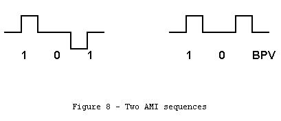
It is important to note that the template of the DS-1 signal is bipolar. This means that a plus voltage, a zero voltage, and a minus voltage are important to the coding of the signal. The code which is used in T1 is call AMI for Alternate Mark Inversion. This means that if a "1" or Mark is coded as a positive voltage, the very next "1" must be a minus voltage or the result will be a Bipolar Violation (BPV).
Figure 8 shows a valid AMI sequence and a sequence with a BPV.
Notice that in the specification in Figure 7, there is reference to the "Maximum Successive Zeros". One of the requirements of the coding sequence and hence the signal shape of the DS-1 is that a "1" bit is sent in order to maintain the timing synchronization. For example, a signal that was sending all 0's would be a constant zero voltage line. Eventually the timing of the system would be lost.
The requirement is that no more than 15 0's can be sent before a "1" must be transmitted. In telephone applications that was accomplished with bit 7. Remember, bit 8 is sometimes used for signalling so it couldn't be universally used. The human ear would never detect these slight variances in the lower order bits. In the case of sending data, using bit 7 and bit 8 for other than faithfully representing the data being presented for transport yields disastrous consequences. Thus a mechanism had to be developed for data only applications.
The easiest approach and a technique still in use in DDS is to make every bit 8 a 1 and to use only the lower 7 bits. This 7/8 mode yields 56Kbps instead of the standard DS0 rate of 64 Kbps. This technique also disallowed the use of signalling bits.
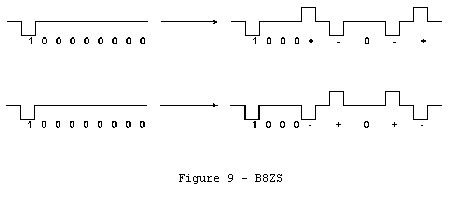
An improvement to this technique was developed known as B8ZS with stands for Binary Eight Zero Substitution. This technique takes advantage of BPV's in the data stream to be decoded as a signal.
With B8ZS coding, each block of 8 consecutive zeros is replaced with the B8ZS code word. If the pulse preceding the inserted code is transmitted as a positive pulse (+), the inserted code is 000+-0-+ (BPV's in position 4 and 7). If the pulse preceding the inserted code is transmitted as a negative pulse (-), the inserted code is 000-+0+- (again BPV's in position 4 and 7).
Figure 9 shows how B8ZS works.
This is the standard for "Clear Channel Capability". AT&T references it in Publication 62411 in Appendix B as CB144. It is part of the ANSI T1.403-1989 standard as well.
Cabling
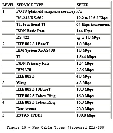
Now for some discussion on ABAM cable. This is the cable that is called out in the DSX-1 spec and is a physical cable that was manufactured by AT&T. Generally it is a cable that has unshielded twisted pairs with a wire size of 22 AWG. Some authorities suggest that it is pulp insulated while others suggest that it is plastic insulated. In any event, ABAM cabling, per se, is no longer available. Modern cable manufacturers, however, especially those active in EIA-568, have developed cables with specific categories or levels. Category/Level 2 cable is adequate for the T1 data rate and has the following characteristics:
- 24 AWG
- 2 pairs
- 100 ohms impedance @ .772 MHz
- 7 dB attenuation/ 1000 ft @ .772 MHz
- 41 dB crosst
all @ 1000 ft.
Several manufacturers make this cable type. A summary of the Category/Level types per RS-568 is listed in Figure 10.
DCB Manufacturers the T-extender, a simple T1 repeater that allows the length of a T1 line to be up to 5,000 ft. It's easy to install, having no switches or settings, and inexpensive at $495.
Connectors
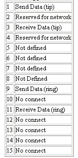
The discussion of connectors sometimes becomes confusing as there is a difference between "de facto" standards, things used in products, and specification. AT&T specify that the Network Interface (NI) should be a subminiature 15-pin female connector with the following pin-out:
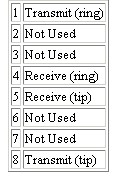
AT&T Publication 62411 further states that "in such cases where ISDN standards need to be met, an 8 pin mini-modular connector is recommended" with the following pin-out:
To complicate the matter, ANSI T1-403-1989 specification calls out for "one of four Universal Service Ordering Code (USOC) connectors (RJ48C, RJ48X, RJ48M, and RJ48H)" with pin assignments as follows:
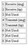
As it goes, the above pin-out and connectors is also the "de facto" standard vis-a-vis how currently available hardware is configured.
Applications
Well, then, what do we do with these DS-1/DSX-1/T-1 signals? There are several applications and specific equipment that can be applied.
- DACS
- D4 Channel Bank
- PBX
- CSU
- T1 Muxes
- SRDM (Subrate Data Mux)
- Fractional T1
The most important issue to see is that there can be T1 networks that are customer owned and T1 networks that use the AT&T Accunet T1.5 system. The applications will be the same but the constraints on the equipment are more stringent using the AT&T connection.
DACS (Digital Access Cross-Connect)
There are three levels of DACS compatibility. The first level is DS-1 and is at the full T1 rate. The second level is "bundled" or 1/4 T1 level. This allows the customer to utilize Customer Controlled Reconfiguration or "fanout" at the CO (central office). The third level is at the 64 Kbps or DS-0 level. What happens is a single T1 signal is generated using channels a and b and goes to the CO. The CO splits this into two T1 trunks one carrying channel a and the other carrying channel b. The device the performs this function is called a DACS. DACS may also be configured with a topology such as a ring topology. If one of the trunks goes down, the data will be reconfigured to go over the standby trunk. In the past, almost all DACS are owned by the telcos; now, many communications users are using DAC functionality on their own networks. DCB can supply a DACS or mini-DACS!
D4 Channel Bank
As we mentioned the T1 signal must somehow be split into the 24 separate and distinct voice channels. When this is done, it is still in the digital form. The codecs must then convert the digital signal (per channel) into analog signals to be sent on the subscriber loops. Again, most Channel Banks tend to be owned and operated at the CO's (Central Offices). Since deregulation in the 1980's, more T1's are owned by users, as telephone carriers continue to reduce the cost of the local loop (the wires from the central office to the customer premise).
DCB can supply a full featured channel bank or full-feature DSU/CSU for full or fractional T1 termination.
PBX (Private Branch Exchange)
Clearly the intended use of T1 was to bring in as many telephone lines using voice as possible through a digitized technique (PCM Pulse Code Modulation). Tie lines between PBXs account for many private T-1 network applications. This is supported through 2 and 4 wire E & M (Ear and Mouth) signalling techniques through the T1 Mux. A 2w FXS (Foreign Exchange Subscriber) function (dedicated line to a distant CO) and 2w FXO (Foreign Exchange Office) function (the CO version) can also be supported by the T1 trunk. In the latter mode, the T1 line acts as an "extension cord". The primary way in which customers use this function is through the T1 Multiplexor.
CSU (Channel Service Unit)
This may be the easiest to explain. A DS-1 comes from the phone company to the customer. This line must be given the proper termination, line protection (vis-a-vis FCC Part 68), and message handling capability. In the old days, the phone company supplied this equipment but today this probably will be CPE (Customer Premise Equipment). The output of the CSU is the DSX-1 signal. The most common CSU is found in a T1 Mux however they can stand alone with various added functionality.
The bipolar output of the CSU can be connected to a DSU (Digital Service Unit) which converts the bipolar signals to unipolar and vice versa at the data rate gleaned from the bipolar signals.
The DCB T-Driver, for example, is a DSU. It takes unipolar data from the terminal and coverts it to a DS-1 signal. In many ways it also acts as a CSU and its transition to a CSU/DSU is quite possible. AT&T Pub 62411 requires that a CSU perform the following functions:
- regeneration
- loopback
- keep alive
The regeneration part is part of the T-Driver functionality. Loopback is commanded from the Carrier in one of two ways:
- in line data pattern with D4 (SF) formatting
- using the FDL with ESF formatting
As the FDL is already being used in T-Driver, it would be rather straightforward to incorporate the appropriate responses to the command structure of the loopback from the carrier. The interface is already surge protected and meets FCC Part 68. The conclusion is that we have with relatively small impact an "ESF CSU" in the T-Driver product that can connect directly to the carrier. To incorporate an "SF CSU" which is still quite prevalent in use with D4 channel banks, would be a more significant undertaking requiring hardware and software changes.
As a matter of note, DDS (Digital Data Service) also requires a CSU but most units are sold as a CSU/DSU with a V.35 or RS-530 connector right on the device. DCB's T1 and fractional T1 CSU/DSUs are examples.
T1-MUX
This is actually a family of devices dedicated for customer use. They are normally T1 or fractional T1 TDMs which comply with format constraints , DACS interfaces, and often have an optional CSU. Their purpose, depending on the number of ports, is to allow transmission of data, image, and voice form many different sources of a single network link.
Many T1 Muxes are also Subrate Data Muxes (SRDMs). By this identification they are able to accommodate synchronous data rates of 2.4, 4.8, 9.6, and 19.2 Kbps. Asynchronous data rates are also allowed in some devices. SDRM operates per DS0.
Since T1 muxes are also DACS compatible at the DS0 level, Fractional T-1 service is also compatible with the devices. They also comply with the D4 channel bank requirements of bit density, zero density, and the provision of clear channel. FT1 is like SRDM only at the DS1 level. Hence, data may be at multiples of 64Kbps.
Also many T1 Muxes allow for the integration of the AT&T Switched 56 service. These are important month-end transfers, CAD/CAM files and teleconferencing.
DCB Products
Data sheets and application notes are available from the DCB web site for all DCB products. Check the Product Index or the Education Section for direct links.
FT Series Fractional T1 DSU/CSU
The FT DSU/CSU's have a DS-1 output signal, and are FCC registered DSU's. They take data at a configured speed via an RS-530/V.35 interface and convert the data to a T-1 data stream. The format of the data is can be D-4 or ESF. The transmitter is configured with a selectable signal attenuator (LBO) of 0, 7dB, and 15 dB per AT&T spec. The FT series is available in a single channel units (FT-1), two channel unit (FT-2) and a 4 channel unit (FT-4). Each port can be configured to use from 1 to 24 of the DS-0's (56 or 64 Kbps each DS-0). The FT-2 and FT-4 units also have drop and insert capability.
T-Extender
T-Extender is a T1 repeater designed to AT&T specifications. This device takes a DS-1 signal and regenerates it as a DS-1 signal. T-Extender can have the DSX-1 output of T-Lan as an input signal and T-Lan will also accept and decode the output of the T-Extender. T-Extender, being a signal repeater, is not constrained by any formating. For example, a BPV is passed through just a readily as a normal signal. The output of T-Extender is -4 dBdsx and is fixed. This is -4db from the allowable power as defined in the Repeater Specification, AT&T Publication TA24/CB113 and was done to simplify the circuit. The product has a robust receiver and therefore should have no difficulty in going repeater to repeater nearly 6000 feet on 22AWG solid, shielded twisted pairs.
DACS
The V 4200 is a versatile 9 or 28 slot integrated T1/T3/OC-3 access device. Depending on the plug-in cards selected, this unit can be configured (a) as a CSU/DSU with drop and insert and voice capabilities, (b) as a multiple E1 to T1 converter or fractions of them, (c) as a digital cross-connect system (DACS), (d) as sets of ICSU combined in one box, and (e) as a channel bank. As a CSU/DSU, data from the V.35 or X.21 port can occupy any fraction of a E1 or T1 port As an E1 to T1 converter, A to law and signaling conversion are correctly handled. For both E1 and T1 ports, continuous error checking, performance polling, and in-service diagnostics are provided. In any of the above combinations, full time slot interchange (TSI) among the ports are possible, making the V 4200 a small DACS (digital access cross-connect system). The ports can further be used in pairs as ICSUs (intelligent CSU) at lower cost and smaller space than individual ICSUs. Lastly, the V-4200 can be configured as a channel bank. By using high speed cards, it can also interface to up to two OC-3 lines.
Appendix A
Definition of dBdsx
A simplified equation for the definition of dBdsx is the following:
dBdsx = 20 X log (.167 Vp-p measured)
where "Vp-p measured" is the peak-to-peak measurement of the voltage between tip and ring. For example...
If there is a 0.5 volt positive voltage on tip and a 0.5 volt negative voltage on ring...
The peak-to-peak voltage measurement is 1.0 volts. Using the equation,
dBdxs = 20 * log (.167 X 1.0) = 20 * (-.777)
= -15.5
Notice that tip and ring signals are inverted. When a 1 is sent one line (tip, for example) will be a positive voltage and the other (ring, for example) will be a negative voltage. When 0's are begin sent, both lines are at 0 volts. Since T1 is AMI or alternating, the next 1 will have the voltages reversed.
Many specifications give the "pulse amplitude" rather the dBdsx. This parameter is the positive voltage, measured from zero, of a 1 being sent. In other words, it is half of the peak-to-peak voltage. As a note of interest, the T1 pulse is not specified as necessarily symetric. AT&T Pub 62411 states that the maximum + voltage is defined as 3.0 +/- 0.3 volts while the maximum - voltage is its absolute value (without sign) and must be within 0.20 volts of the + voltage but no less than 2.7 volts or greater than 3.3 volts.
Wizard Simplifies Development
DSC provides IVR software including our IVR wizard development tool for creating interactive voice response applications.
Our IVR software lets you increase IVR development productivity by providing a visual development environment. IVR applications can be defined in minutes using this sophisticated, yet easy to use development tool.
DSC also has available a comprehensive IVR software library known as our IVR Wizard Software Development Kit. This optional package is available for programmers and systems adminstrators who wish to manage IVR programs fromLinux IVR, Unix, or Windows IVR operating environments.
Data collected by your phone ACD (Automatic Call Distribution) or IVR (Interactive Voice Response) systems can be passed to your existing PC, Unix or Web applications through our phone software.
The PACER predictive dialer can automatically call your customers and pass only connected calls to your agents. With our computer telephony software, your telephone and computer work together to provide cost-saving benefits.
|